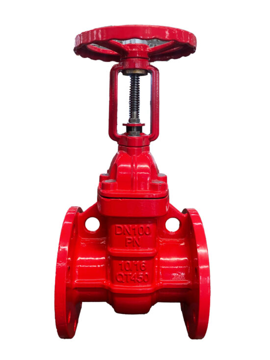
Email

xhyvalve@cigatevalve.com

Call us

+86 131 3174 5026

what-is-a-pressure-control-valve?

  1. Home
  2. »
  3. knowledge
  4. »
  5. valves-basics
  6. »
  7. what-is-a-pressure-control-valve

Table of Contents

01 What is a Pressure Control Valve?

A pressure control valve is designed to regulate the pressure within a hydraulic system. Its primary role is to prevent damage caused by excessive pressure by either relieving pressure or maintaining a desired set point. Pressure control valves can be categorized based on their function, including relief valves, reducing valves, and more.

Pressure control valves are essential in hydraulic applications such as construction machinery, industrial automation, and fluid systems, where maintaining optimal pressure is crucial for smooth and safe operation.

02 Pressure Control Valve Components

This diagram provides a clear and detailed breakdown of the components of a pressure control valve. Each part is carefully labeled, showcasing its function and placement within the valve assembly. Key components include:

  • Valve Body: Serves as the main structure, housing all internal parts.
  • Diaphragm: Regulates pressure by flexing in response to flow changes.
  • Spring: Controls the movement of the seal disc, ensuring smooth operation.
  • Seal Disc and Seat: Prevent leakage and maintain a reliable seal during operation.
  • O-rings and Bearings: Ensure tight sealing and reduce friction between moving parts.
  • Cover and Cover Plug: Protect internal components and allow easy maintenance.

This diagram is an essential resource for understanding the structure and functionality of a pressure control valve, designed to aid in assembly, maintenance, and troubleshooting.

Stem

The cylindrical rod that connects the gate to the actuator, allowing the gate to be moved in and out of the flow path.

Gate

The rectangular or circular metal plate that slides between the sealing surfaces to open and close the flow path. The gate is typically thin and sharp, resembling a knife, which gives the valve its name.

Packing

Knife gate valve packing, also known as stem packing or gland packing, consists of flexible rings or braided materials nestled around the valve stem within the packing box. These rings create a tight seal, preventing leakage of the contained fluid while the stem moves up and down to open and close the valve.

Seat(Resilient)

In knife gate valves, where a sharp blade slices through fluids and solids, the resilient seat plays a crucial role in achieving a leak-tight seal. This crucial component directly contacts the blade, ensuring no fluid escapes even with challenging materials.
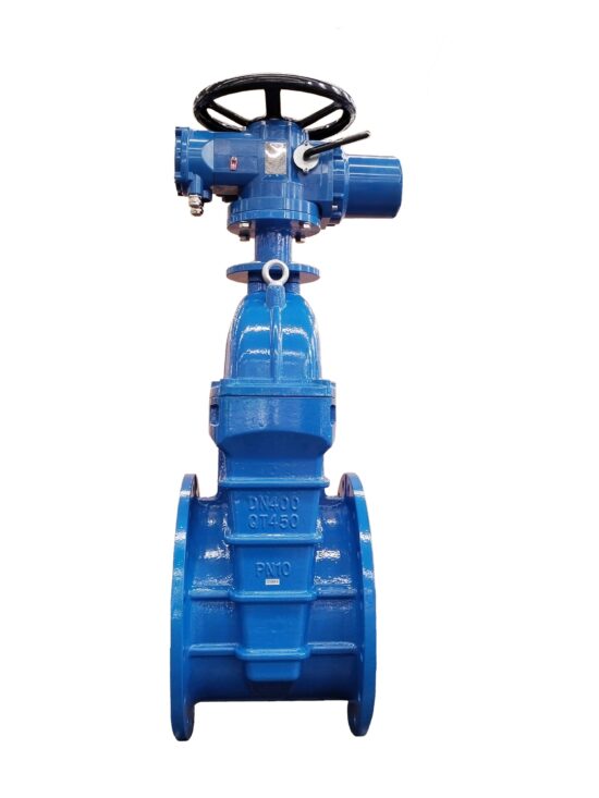
Yoke or actuator

The yoke is a structural component that supports and guides the movement of the valve stem, which is connected to the gate.
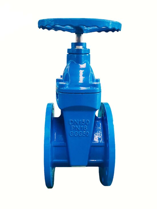
Body

The knife gate valve body is the central housing that encloses all the crucial components of this robust valve. It serves as the foundation for withstanding various pressures, temperatures, and demanding flow conditions.

Epoxy coating

Epoxy coatings are applied to the internal surfaces of knife gate valve bodies and components to enhance corrosion resistance and improve the overall service life of the valve.

03 Types of Pressure Control Valves

There are several types of pressure control valves, each with unique functions tailored to different system requirements. Let’s look at some of the most commonly used types:

  1. Pressure Relief/Sustaining Valve

A pressure relief valve (PRV) is typically used to protect a system from exceeding a preset pressure limit. When the system pressure rises above the desired threshold, the valve opens and diverts excess fluid, preventing damage to the hydraulic components. This type of valve is often found in systems that require consistent, controlled pressure for safe operation.

On the other hand, a pressure-sustaining valve ensures that downstream pressure remains above a set level, even when the upstream pressure is lower. This type of valve is critical in maintaining consistent pressure in secondary circuits while still allowing the primary circuit to operate within safe limits.

  1. Solenoid Control Valve

A solenoid control valve uses an electrically controlled solenoid to adjust the valve’s position. By changing the current in the solenoid, the valve can control the flow and pressure of fluid. This type of valve is ideal for automated systems where precise control is necessary. They are commonly used in systems requiring remote operation and automation, offering fast response times and high efficiency.

  1. Remote Float Control Valve

A remote float control valve is used to maintain a constant pressure in one part of the hydraulic system while another part is subject to varying pressures. This type of valve can be remotely controlled, making it ideal for applications where the load is not constant or when the pressure in the system needs to be adjusted dynamically. These valves can be used in complex hydraulic circuits, such as those found in industrial equipment, to ensure smooth and safe operation.

  1. Pressure Reducing Valve

A pressure reducing valve (PRV) limits the pressure in a specific part of the hydraulic circuit, usually downstream of a higher-pressure system. It is essential when different parts of a system require different pressure levels. This type of valve is often used in applications where a secondary circuit needs to operate at a lower pressure than the main circuit. It ensures that the pressure in the secondary circuit stays at a constant, lower level, regardless of fluctuations in the main circuit’s pressure.

  1. Bi-Level Float Control Valve

A bi-level float control valve is a specialized type of pressure control valve that allows for two separate pressure levels to be controlled independently. This valve is often used in systems where two different pressure zones need to be maintained at the same time. For example, it can be used to control pressures in both high-pressure and low-pressure zones within the same system, allowing for greater flexibility and control over complex hydraulic systems.

04 Principle of Operation

On-Off Modes

On-Off pressure control valves operate with two distinct positions: fully open or fully closed. This is achieved through a series of pressure manipulations within the control chambers:

  • Closed Position: Line pressure is applied to the upper control chamber, creating a superior force that moves the valve to the closed position. This ensures a drip-tight seal and prevents any flow through the valve.
  • Open Position: The valve opens when the pressure in the upper control chamber is released to the atmosphere or a lower-pressure zone. The remaining line pressure acting on the seal disc then moves the valve to the open position, allowing flow.
  • Powered Open Position: In this state, line pressure is directed to the lower control chamber while simultaneously venting the upper control chamber. The combination of these pressures, along with the force exerted by the line pressure on the seal disc, drives the valve to the fully open position, ensuring maximum flow.
  1. Solenoid Control Valve
    Closed Position: When de-energized, line pressure is applied to the upper control chamber, generating a force that keeps the valve closed. This ensures no flow through the valve.
    Open Position: When energized, the solenoid pilot opens, venting the upper control chamber to the atmosphere or a lower-pressure zone. Line pressure acting on the seal disc moves the valve to the open position, allowing flow.
    Powered Open Position: Line pressure is directed to the lower control chamber while the upper chamber is vented, creating a force that fully opens the valve for maximum flow.

  2. Bi-Level Float Control Valve
    Closed Position: The valve is kept closed when the float mechanism senses that the water level is within the desired range. Line pressure applied to the upper control chamber ensures a tight seal.
    Open Position: When the water level drops below the set range, the float mechanism activates, venting the upper control chamber. Line pressure moves the valve to the open position, allowing water to flow in.
    Powered Open Position: For systems requiring fast filling, line pressure is directed to the lower chamber while venting the upper chamber, ensuring rapid valve opening and maximum flow.

2-Way Modulating Mode

Valves operating in 2-Way Modulating Mode provide intermediate control positions to maintain a preset system pressure. They adjust dynamically to line pressure changes:

  • Closed Position: When the pilot valve traps line pressure in the upper control chamber, the superior force causes the valve to move into the fully closed position, ensuring a drip-tight seal.
  • Modulating Position: The pilot valve senses line pressure changes and modulates the valve to an intermediate position. This stabilizes the downstream system pressure by releasing or accumulating pressure in the control chamber.
  • Open Position: When the pilot valve opens, it vents the upper control chamber. The line pressure acting on the seal disc and lower control chamber moves the valve into the open position.
  1. Pressure Reducing Valve
    Closed Position: The adjustable pilot valve traps line pressure in the upper control chamber. This creates a force that moves the valve to the closed position, ensuring no flow.
    Modulating Position: The pilot valve senses downstream pressure and adjusts the control chamber pressure accordingly. The valve modulates to an intermediate position to maintain the preset downstream pressure.
    Open Position: When the pilot valve releases pressure from the upper control chamber, the line pressure acting on the seal disc and lower control chamber opens the valve, allowing flow.

3-Way Modulating Mode

Valves operating in 3-Way Modulating Mode provide enhanced control by managing pressure between three zones, offering precise downstream pressure regulation and preventing hydraulic lock:

  • Closed Position: The pilot valve detects high downstream pressure and introduces upstream pressure into the upper control chamber. The double-chambered design enables powered closing, even at zero flow.
  • Modulating Position: When downstream pressure equals the setpoint, the pilot valve freezes the valve in an intermediate position. This balance allows the valve to respond dynamically to downstream pressure fluctuations by either venting or pressurizing the upper control chamber.
  • Open Position: If downstream pressure falls below the setpoint, the pilot valve vents pressure from the control chamber. This causes the valve to fully open, reducing pressure loss and maintaining maximum downstream pressure.
  1. Pressure Relief/Sustaining Valve
    Closed Position: When downstream pressure exceeds the setpoint, the pilot valve directs upstream pressure into the upper control chamber. This creates a force that closes the valve, preventing over-pressurization.
    Modulating Position: The pilot valve responds to changes in downstream pressure, venting or pressurizing the upper control chamber. This modulates the valve position to maintain the desired pressure.
    Open Position: If downstream pressure falls below the setpoint, the pilot valve vents the control chamber. Line pressure acting on the seal disc fully opens the valve, ensuring downstream pressure is sustained.
  2. Remote Float Control Valve
    Closed Position: The float mechanism directs upstream pressure to the upper control chamber, closing the valve when the water level reaches the desired height.
    Modulating Position: As the water level fluctuates near the set range, the float mechanism adjusts the pilot valve. This modulates the control chamber pressure, allowing the valve to partially open or close to maintain a consistent level.
    Open Position: When the water level drops significantly, the float mechanism vents the upper control chamber, fully opening the valve to refill the tank or reservoir.

05 Benefits of Using Pressure Control Valves

Pressure control valves offer several benefits, including:

  • Safety: By regulating pressure, these valves prevent system overloads and equipment failure, ensuring safer operations.
  • Efficiency: Pressure control valves help maintain optimal working conditions, reducing energy consumption and improving the efficiency of hydraulic systems.
  • Longevity: Proper pressure regulation prevents excessive wear and tear on components, extending the lifespan of hydraulic equipment.
  • Cost-Effective: By preventing damage to the system, pressure control valves can help reduce maintenance costs and downtime.

06 Conclusion

Pressure control valves are essential components in hydraulic systems, ensuring safe and efficient operation. Whether you’re using pressure relief valves, solenoid control valves, or pressure-reducing valves, each type plays a unique role in maintaining optimal system pressure. By understanding how these valves work and where they are applied, operators can ensure smoother, more reliable performance in a variety of industries.

By selecting the right pressure control valve for your specific needs, you can protect your equipment, optimize performance, and enhance the efficiency of your hydraulic systems.

Do you have any further questions regarding gate valves or are you looking for a suitable solution for your water application? Please use our contact form to get in touch. 

Submit An Inquiry

Consent Management Platform by Real Cookie Banner